Hygrade Casting will be closed from 20th December 2024 and re-opening again 20th January 2025. Merry Christmas & Happy New Year!

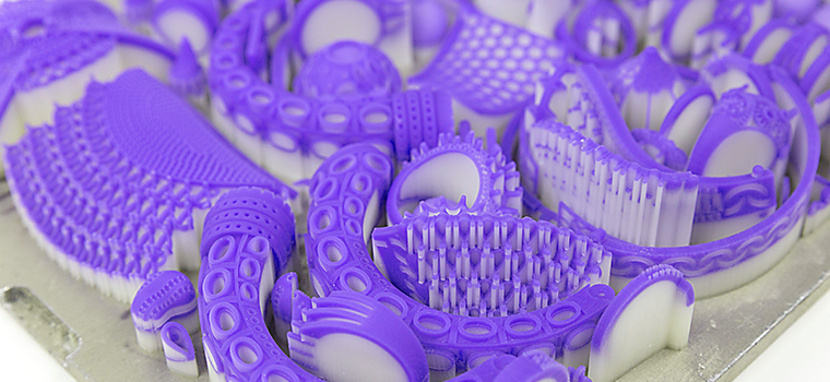
3D Wax Printing

We’ve invested in the latest generation of high-precision 3D wax printers from the United States to provide exceptional accuracy, consistency, and casting reliability. This service is engineered to meet the demands of professional jewellers.

This page outlines technical requirements that your CAD designer must follow. Please read it carefully before submitting files—adhering to these specifications is essential for successful casting outcomes and great castings start from great CAD files.

3D Wax Printing

We also accept customer-supplied waxes, including:

  • 3D wax prints
  • Pump injection waxes
  • Hand-carved waxes
We also accept customer-supplied waxes, including:

3D Printing Technical Details

We print at a 16 μm (micron) layer thickness using XHD (Extreme High Definition) 1200 × 1200 × 1600 DPI resolution. This standard we provide delivers outstanding surface detail and dimensional accuracy, striking the ideal balance between quality and cost-efficiency for the jewellery industry.

For uber-high budgets (10-30x above our normal 16 μm printing fees) and specialised projects, we offer printing at 8.8 μm and QHD (Quality High Definition) 2000 × 1800 × 2900 DPI. However, the visual difference between 16μm and 8.8 μm is virtually indistinguishable to the human eye even under magnification post-casting, so QHD printing is rarely necessary for the jewellery industry.

CAD Meshing Requirements

We do not accept poorly meshed STL files. Mesh quality directly impacts both print accuracy and casting results. It is the CAD designer’s responsibility to provide clean, properly meshed files.

  • STL mesh tolerance must be set to 0.015 mm.
  • Tolerances above 0.015 mm (ie 0.016mm) will degrade print resolution.
  • Tolerances below 0.015 mm (ie 0.014mm) offer no visual improvement and only increase file size and upload times.
CAD Meshing Requirements

CAD Sprue Requirements


Sprues must be designed into the CAD file before submission

Due to the fragility of 3D printed wax (which melts at just 35°C), we do not attach sprues manually.

  • Every item requires a custom sprue for structural integrity and proper metal flow.
  • If no sprue is included, your file will not be printed or cast, as we cannot guarantee satisfactory results when sprues are added by hand.
Why Y-Shape Sprues Matter:

Straight sprues are acceptable in some cases such as pendants or bangles, but for rings, we strongly recommend Y-shape sprues. Ring castings are far less forgiving, and the margin for error in precious metal casting is incredibly slim.

We’ve seen too many miscasts and shrinkage porosity issues caused by thin, straight sprues, often chosen to save on metal. These shortcuts come at the cost of reliability and finish, which isn’t compatible with the calibre of quality our clients demand.

The Y-shape sprue offers key advantages:

  • Faster and more stable metal flow, reducing the risk of miscasting and porosity
  • Extra material ("meat") at the base of the shank, allowing for proper profiling without compromising its geometry

In the first image, you’ll see a front view of the Y-shape sprue. The two images below show the side view. Note how the red sprue pinches inward, this preserves the shape of the shank, while the Y-branch compensates to maintain the faster flow characteristics despite the restriction.

Sprue tip diameters:

  • 2 mm for small to standard-sized pieces
  • 1 mm for larger, thicker, or bulkier items

Short-cuts and cost saving measures don’t pay off, deviating from the recommended sprue size or shape, even slightly can cause costly failures, delays and unhappy clients.

Why Y-Shape Sprues Matter:
Extra “meat” to ensure the perfect profile

Important: Adding a one size fits all sprue is not the right way of doing things (it's a short-cut some CAD designers try get away with). CAD designers must model “extra meat” at the sprue join (e.g. base of shank). This gives jewellers enough material to de-sprue and finish the piece without flattening or warping the shape.

In the below image 2 images, we understand CAD designers may look at our sprue design first and say “it wont print” (in this instance they are CORRECT). You can see in the below images, there is a empty space between the sprue and the ring. Naturally, many CAD designers have been “pushing” the sprue into the profile of the ring. After your jeweller cuts and files the sprue, you may have a not perfectly round shank at the base. Please note the gaps represented below are over-emphasised for web display purposes, in the real world it's usually around 0.50mm "extra meat" where the sprue connects to the shank.

Extra “meat” to ensure the perfect profile

In order to avoid this issue and to have the perfect shank profile, your CAD designers must model in extra meat to fill up the empty space (so that it can print successfully) and your jewellers can have meat to work with when filing away the sprue.

Shank Profile
Shank Profile
Shank Profile

You can see the left image, we have displayed only half of the empty space filled up (highlighted in pink), the middle image is only shows an "over-emphasised" gap for web display purposes, and the third image is fully complete. This is how your CAD designers can fill in the empty space correctly to ensure perfect geometry.

Flow Gate Requirements

Flow gates must also be included in the STL file you send us. They are critical for ensuring that molten metal reaches all areas before it begins to solidify. If you are casting a plain band without a centre stone or without a windowed setting work on the shoulder/side of the band, flow gates are not necessary.

Why flow gates are essential:

  • Molten metal begins cooling immediately after leaving the crucible.
  • Gold solidifies within 2 seconds after leaving the crucible and entering the flask.
  • Proper flow gates minimise miscasts and shrinkage porosity.

Minimum Flow Gate Diameters (green in images): 1.40mm

The reason we state 1.40mm is not only to ensure gold can flow fast enough to the setting work, but to also ensure the gates don't break off during the wax dissolving process. We found that 1.2mm gates provided a 50% breakage rate during wax dissolving, 1.3mm gates provided a 30% breakage rate and 1.4mm provided only a 5% breakage rate (meaning 95% of wax prints that contained a 1.4mm flow gate did not break during the wax dissolving process). Furthermore the larger the flow gates provide less shrinkage porosity and a significantly lower mis-cast rate.

Example ring 1:

A ring with a simple setting on the top and no window shoulder diamonds, only requires 1 simple straight flow gate to the setting as per image.

As you can see, the ring represents yellow gold, and only requires a 1.40mm flow gate (green) and a sprue tip diameter of 3.2mm (red).

Example ring 1:
Example Ring 2:

A ring with setting work on the side that also has holes/windows in the side of the setting requires a Y shape flow gate (green) in order to ensure metal can fill up fast enough between the setting work. Not having this Y shape increases the chances of miscasting and/or shrinkage porosity significantly, the flow gates shown are 1.40mm (green), whilst the sprue tip diameter is 3.2mm (red).

Example Ring 2:
Example Ring 3:

A thick and chunky ring require thicker sprues, this is simply a matter of your CAD designers working in proportion to your ring. The below example sprue has a tip diameter (red) of 4.10mm. The purpose of putting the main feeder sprue at the heavy section of the ring is to ensure metal to flow fast enough to the thinner sections (instead of thin trying to feed thick). By doing this method, we are able to eliminate shrinkage porosity, brittleness, miscasting and finger sizing issues due to shrinkage, in a ring of this nature (no setting work), flow gates are not required.

Example Ring 3:
Example Earing 1:

A stud earing, setting, pendant etc etc in this format simply requires the flow gates to meet every tip/claw to the exact size. The green flow gate can simply “pinch in” a tiny amount to the tip of the claw as a visual indicator for your jeweller to know where to cut. If your claws are 2mm diameter, ensure the flow gates (green) coming off the red sprue are 2mm in thickness and then “pinch in" to 1.80mm where they need to be cut, the red sprue tip diameter is 3.20mm

Example Earing 1:
Example Pendant Nameplate 1:

Long designs require multiple gates for consistent flow. Yes, the gates and sprue may weigh more than the item itself—but this ensures successful casting. We rather provide you solid information to receive excellent healthy castings as opposed to dealing with the potential of miscasting and shrinkage porosity by trying to “save” on the sprues/flow gates.

The green flow gates in this example are 1.40mm each and the red sprue tip diameter is 3.20mm.

Example Pendant Nameplate 1:
Example Bangle 1:

The below bangle is in 2 pieces, in this example, the flow gates are approximately 2.50mm in diameter and you can see a bar running across with tabs sticking out. Again this style of flow gates is crucial for a successful casting of bangles. Thicker bangles require thicker flow gates. The tabs running across the main bar are simply to give us a bit more meat as a contact point when we attach the thick main wax sprues to the flow gates.

The cost difference in printing thin (1.40mm) vs thicker (2.50mm) flow gates is insignificant, we don’t work by charging a premium markup for wax printing weight per gram but rather charge a competitive rate for the entire job that ensures you have a clean and successful casting.

Example Bangle 1:

Full Band Setting Rings – Special Requirements

For rings with settings that go all the way around the band (leaving no external surface to attach a sprue), a specialised setup must be designed directly into the CAD file. This section explains how and why.

Centre Sprue (Red)

The centre sprue (red) must be: 4.10 mm in diameter

At the top of the sprue, you’ll notice a half-ball shape, this isn’t just decorative, it serves a critical function and purpose. The half-ball acts as a mini reservoir to counteract metal shrinkage during solidification.

As molten metal cools, it naturally contracts. If there isn’t enough feed metal nearby, the ring can “pull back,” leaving a sunken or porous area. The half-ball ensures there’s a buffer of extra metal ready to feed as the ring shrinks during cooling, thus resulting in a solid, clean and successful casting.

Flow Gates (green)

The green flow gates branching off the sprue:

  • Minimum of 4-7 gates for small ring sizes
  • Minimum of 8 gates for larger rings
  • Diameter of flow gates (green) 1.80mm (or more for thicker/wider bands)

Each flow gate is angled upwards, not flat, this is deliberate as upward angles help metal flow faster and more evenly around the band before it starts to cool and solidify, thus reducing the risk of incomplete fills, weak spots and porosity.

Also note where the gates are attached: they’re connected to solid surfaces, not open holes or windows. This small but important detail saves your bench jeweller and setter time. By anchoring to solid areas, there’s no need to drill through blocked settings or remove unwanted casting remnants in delicate spots.

These types of items are cast separately from standard pieces. We apply specific methods for casting to ensure clean and successful casting results for these items.

Full Band Setting Rings – Special Requirements

Shrinkage Compensation

Our 3D wax printers operate with zero print shrinkage, and for most average-sized items, furthermore we can cast with no shrinkage with wax with most regular items as we have perfected our metal formulas, melting temperatures, flask temperatures and our quenching times. However keep in mind each jeweller is different, some jewellers are heavy handed on the tools and may require up-scaling to factor in their heavy handedness (ie you might need to add 1% shrinkage compensation to counter-act their heavy handedness).

However, due to the nature of metal casting, where molten metal is poured into flasks that are not as hot, then rapidly quenched in water, some shrinkage can occur on larger thicker items like thick bulky signet rings or thick and bulky bangles. To compensate, we recommend increasing (up-scaling) your design dimensions by 0.50-1.00% for large, thick and bulky pieces.

If you're casting for a master for mould, a larger allowance of 2 - 4% may be required. Please note that we do not take responsibility for shrinkage issues related to master moulds, as there are many external variables beyond our control, such as whether you're using liquid silicone vs vulcanised rubber, or cold vs hot moulding methods. Best to consult with the manufacturer for guidance.

Final Notes

To keep things running smoothly and ensure top-quality results, STL files must meet the specifications outlined above. Files that don’t may be rejected, not to be difficult, but to protect your work and avoid delays or failures.

Whether you're casting two rings a week or two hundred, the fundamentals don’t change: clean castings start with clean files. Our workflow is designed for professionals jewellers, CAD designers, and retailers who take quality and precision seriously.

We don’t charge extra printing fees for thicker flow gates as the wax cost difference is typically under 10 cents. We ask for proper gating because it prevents breakages, shrinkage porosity, and miscasts all of which waste time and money.

Yes, thicker gates will require slightly more metal, however keep in mind we offer some of the competitive printing and metal rates in the country.

We’ve seen it often: a jeweller tries to save a fraction of a gram on flow gates, only to end up with cracked waxes, failed prints, or poor castings. We don’t charge for miscasts, but they cost us, upset you by causing delays which is why we insist on technical accuracy from the very start.

Our clients range from independent jewellers to national retailers with hundreds of orders per week. What they all have in common: they follow spec, care about quality, and trust us to deliver clean, porosity-free castings every time.

Please ensure:

  • Your CAD designer understands casting requirements.
  • STL files are watertight, complete, and correctly sprued with suitable flow gates.

This is a technical process. Great castings always start with great files.
Whether you're a one-person workshop or a multi-store operation, if quality matters, we're the casting house that delivers.

3D Resin Printing/Casting – Important Information

We no longer print or cast with resin anymore and we no longer accept customer supplied resins. Many countries around the world have already phased out resin casting in precious metals, and we anticipate most (if not all) Australian casting houses will follow suit by the end of 2025.

This decision was made by us due to changes in resin formulations by the resin manufacturers who are providing zero support and information to casting houses. These formulation changes have resulted with extremely poor casting results such as:

  • Printing failures
  • Miscasting
  • Porosity
  • Shrinkage/Expansion in finger & stone sizing

We have come to the conclusion that resin casting has taken a step backwards in terms of casting quality and consistency, additionally, ongoing research has highlighted increasing health risks associated with resin exposure, and we prioritise the well-being of our workers.